Showing posts with label Type study. Show all posts

Sunday, September 23, 2018

Characteristics of wooden moulding planes Part 1

We seen earlier that the explosion of various ever changing, moulding profiles, created a need for mass produced moulding planes. These planes having a 200 plus years of production, went thru a few changes throughout their manufactures.
We can then used these changes to attempt to date their productions.
Yes, I said attempt,  because just like Stanley and others Type studies, not all changes were followed by everyone and some old timer features lingered on with smaller rurals makers.

Nonetheless, we can used some of these features to come to a reasonable time line and their place of origins.

For a simple looking tool, there is a lot of small details that make or break these wondrous tools.
Get the details right, and they works a treat, get them wrong and you have simply a hunk of wood with a metal blade, not a working tool.

Construction style

There were typically two styles, throughout history.
First came the open mortise style, attributed to the Romans, but lately often referred to as the French Roubo planes, because it shows up on plates in his books.
This style is still to this day, made in Continental Europe.
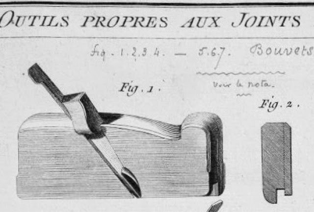
From Roubo
Notice the side finial on the wedge and the snick iron


Typical French plane, 19th century. See the different color on the sole?
They often used Cormier wood as boxing, whereas in the British tradition, 
they used Boxwood (from Turkey, mostly)

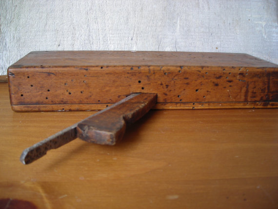
The pin holes are wormhole's, 
Typical in Continental planes. Guessing since they used a lot of fruit wood?

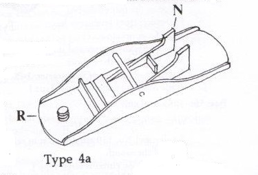
The other style is attributed to the British planemakers and featured a close mortise to capture the wedge.  This is the style most often found, here in North America

Unlike the open sided mortise in the Roman/Roubo style, 
the British style featured a close mortise for the wedge.
All the required shapes are excavated from a solid block of wood, 
nothing is added after, such as in the French types


Type of wood used

Traditionally, Beech was the wood used, but there were regionals exceptions
English, Americans and Canadians planemakers used primarily Beech.
But the earlier ones made in the Colonies  (North America) were often made using Yellow Birch. Roughly 1760-1800.
And notably, Canadian planes of this early era, tend to have tighter grain (older growth wood)
as compared to their British and American cousins

Continental makers (Europe) tend to used fruit wood: Apple, Pears, Persimon etc.
The French used lots of Cormier wood, a fine tight grain fruit wood (Sorbus Domestica)
They also used it for boxing moulding planes soles instead of using Boxwood.


Length of plane

It does not take long before all these moulding planes start to accumulated, it would be nice if they were all of the same length, for ease of storage...
It took until the early 19th century before they started to standardize to a length of 9-1/2 inch long.
Therefore when you come accross a longer plane, it is probably older.
A 10 inch moulding plane for example would indicate, at first glance, an 18th century example.
Just remember that some features lingered on with some makers. Sadly, some have been truncated in the past in order that they all fit together nicely...
But luckily for us, enough details should remained to help us identify it correctly

From L-R
12 inch, 10 inch, 9-1/2 inch and 9-7/16 inch long
Imagine trying to store those in your tool chest or plane till.
And add a few more in between for good measure, yes, its annoying 

The 4 planes I picked
The longest one is interesting because the hand hole grip in the stock is a feature
 normally seen on Roman planes. The front round hole was to put in a dowel to act as a pull handle. Sometimes these front holes have been added later by some users, but on this one, it look original. 
And so appears to be the wedge which has a definitively round shape
It does have a very faint makers mark (Maltese cross??). Unidentified by me so far
Notice also the wedge shapes and the different bedding angle for these planes

An original Roman plane, made of bone, why it survived so well, and has a riveted metal sole.
Presumably, the wooden wedge is missing
Pic from online...

The cutter(s)

The vast majority will be found having a tool steel bit forged welded to a softer carbon steel blank or wrought iron. Some Americans plane makers were known to make the entire  blade of tool steel. They stand out from the crowd, by having a shinier blade, which is a lot more ridgid.
Sometimes, the whole profile is divided in two separate cutters. Mostly found on English planes.

Sometimes will you find the blade maker stamp on these narrow tangs, the British, notably, used some markings in their earlier planes. Just like their bigger cousin, the bench planes, rarely did the planemakers made their blades, sourcing them from ironmongers or directly from the forge or manufacturer.
Knowing which planemakers used whose blades, help us identify which ones have original blades.

R. HILDICK  1780-1820
Used in these planemakers
T. OKINES
G. MUTTER
C. GABRIEL
W. TAYLOR
STEWART (This blade was found in my Stewart plane)
E. DABBS
STOKOE
T. PORTER
JOHN GREEN
CAULDWALL
HAMBLETON
HAYES

Yes, that blade is from a Mathieson plane, 
and I am not sure if ALL his blades were ALWAYS stamped??
That one predate & SONS

Williams Butch 
Predate Williams & Samuel Butcher. 
These two were brothers.
Started in 1819, by 1822 he began to melt cast steel.
W. BUTCH WARRANTED CAST STEEL is stamped on most of  his blades
Obviously, the small tang may have prevented the full stamp, 
or it is before he started melting cast steel?

Often times the stamp will be found improperly struck or truncated altogether

On this blade tang, the top line is truncated, but we can make up the manufacturer
HUMPHREYSVILLE MFC. Co
WARRANTED CAST STEEL

A different blade from same plane maker. (James Kellogg Amherst Mass. 1836-1886) 
Not easy to center properly a two line stamp on that narrow tang. 

Hard to see but this is severely truncated (more than half) Humphreysville MFC Co Warranted cast steel stamp.
No, the tang was not shorthened, simply poorly stamped

Humphreysville Manufactory Co history is a tad convoluted, I'll try to get it straight:
It was an American company located in Seymour Connecticut since 1806.
They were manufacturing mostly auger bits until a fire destroyed the factory and it was rebuilt in 1852 (In a brick building).  That is when they started to make other edge tools, plane irons and chisels.
And the name?? Seymour was called Humphreysville until 1850, but they kept the old name

You will sometimes come across Roman numeral scratches marks on the blade tang.
That was a system the maker used to keep track of which blade/wedge/body were matched during manufacture. No two planes being exactly the same.
You will sometimes find corresponding pencil marks on the wedge and body.  Being pencilled in, they often disappeared thru the years :-(


A quick look at the sole and how well the blade profile match it, goes a long way to eliminate miss matched examples.  Unlike bench planes, these moulding planes never saw as much usage, hence, they rarely, if ever, would had their blade used up and replaced in their working life.

Good match

Good match

Mismatched, wrong blade

Since striking moulding is usually done on straight grain material, and in preparation a Rabbet plane removed the majority of the material, the cutter(s) do not have to be super sharp and they will stay sharper longer. The cutting surface left is further polished (burnished) by rubbing wood shavings along its profile.
A similar operation still done by turners on the lathe.

The wedge

Most makers carried on the traditions they learned from their masters, as part of their apprenticeship.
Nonetheless, regional differences shows up, and enough examples have comes to light to correlate the specific shape of the finial to a given maker.

Another feature which shows up early, was to make a small relief cut under the wedge finial in order to tap the blade tang without hitting the finial (too much)

Two early American moulding planes, notice relieved wedge
Bottom one is Joe Fuller
pic from Best thing

In addition, the shape went from a mostly circular shape to an ellipse, most of the numerous one
to be found, would have the later ellipse shaped finial, being from the middle 19 th century

The Elliptical shape from the later 19th century.
With the advent of machinery, wedges tended to become all alike.
There were of course, still regional differences

On this Auburn No 177 3/4 in Dado plane, you can see both styles.
The front spur(s) cutter wedge has a more roundish shape, while the main blade wedge has a definite elliptical shape 

This plane is 10-1/4 inch long and has a definite round wedge finial
Samuel Holbeck, London 1730-1770
Auction pic 

Continental European planemakers seems to have never adopted the round style and continued to this day to make rather blockish wedge. Ugly but perfectly functional.


ECE Rabbet plane (German)
Typical blockish wedge shape on Continental planes

Unfortunately, since the wedge can be detached from the plane, they tend to go Missing In Action (MIA) or are sometimes to be found like a dog chew it (NO was not Rudy :-), being wood and abused with a hammer, they break and get replaced.

If you are lucky, the blade, the wedge and the plane bed will all have the matching Roman numerals marks. Yeah, if you are lucky... But if it does, its a confirmed match

And, don't read that too loud, but sometimes, us collector (and users) will easily misplaced the wedges and have them swapped.
Don't panic, you did took pictures of it as received first, right? :-)

Makers marks, Hardware dealers marks  and Owner marks

The preferred location for stamping their brand was at the top front end of the plane, the toe.
It was quickly discovered that the end grain would take a better imprint, crisper, than on the long grain on the sides.
The type and shape of the imprint changed thru the years.


 (ZB) Zig-Zag border

Stamped on a maple body
pic from Pinterest, but guessing from Peter Follansbee


(Inc) Incluse border

THOs L. APPELTON (inc)
BOSTON (zb)


The font used was mostly Roman and the size was pretty well uniform
Earlier ones are seen with Upper case first initials and Lower case for the remainders of the name

Script or Cursive font
MELVILLE (in large script font)
Thomas Melville, Aberdeen Scotland -1820-
I brought this plane back from my first TD to RAF Kinloss, Scotland in the 80s 
That plane body has a thick coating obscuring the marks and the wood grain

Location of maker
Either a street address, or just a town name

M. READ
BOSTON
1842-1844
A ROBERTSON is an owner name
This is a side rabbet plane

AS LUNT
297 HACKNEY Rd
LONDON
and has a Goat head -1880
Similar goat head as used by COX LUCKMAN, (1843-1862) 
then & SON (1894-)
N Steward and Maxey are previous owners

Hardware store dealers, or tool distributors.
Some imprints were not from the maker but simply stamped with the distributor name on it.
Others, carry both stamps.
When a hardware store dealer stamp is found, if you happen to found out when they were operating, where, you have a bonus clue

MELHUISH
 FETTERLANE
Richard Melhuish & Sons were a retail business that operated in Fetter lane, Holborn in London UK 
Melhuish planes were made primarily by Thomas Norris or Stewart Spiers
1828-194x? Saw a 1933 Ad.

Ad from 1892

Ad from Aug 1933

Other have simply, owners stamps on them, often repeated on a few locations.
The style of owner stamps details, lag those of the makers stamps changes.

Finally, both makers and hardware store dealers used also paper labels on some planes.

MARPLES PLANES BB
Mid 20th century
Label on a coffin smoother, this example, but they also used similar decals
 on some of their moulding planes, the BB series

Being paper of water transfer decals, they do not tend to survived long IF the plane was used much

This was getting too consuming and long, I split it in two parts.
Next part, the spring angle and the finishing details on the body.

If anyone want to add to it, omission or additions, please let me know

Bob, who has bigger piles of planes accumulating upstairs, hum, better get on with it :-)


Wednesday, March 29, 2017

The commun Stanley No 110/120 block planes

Stanley manufactured numerous versions of the ubiquitous block planes.
From the small model makers ones to the larger fully adjustable  ones.

The model in question, the No 120 was manufactured from 1876 to 1947 (Walter) It does not shows up in my Stanley Catalog No 34 of 1949
but some claim they were made until the 60s...??

It was never designed to be a great block plane, suitable for cabinet makers (you would be better off with a No 18, 9-1/2 or 60-1/2), it is more geared toward a general household usage. Trimming sticky doors, windows and etc.
And yes plane off paint on a workpiece, instead of using your "good" planes
It is designed as an inexpensive adjustable (blade advance mechanism) block plane for household usage. It was an offshoot of their popular No 110 which does not have a blade advance mechanism.

As Ralph discovered, its achilles heel is in the fragile blade advance mechanism. Definitively not for the ham fisted users... The small serrations on the movable lever are easily stripped if you try to adjust it without slacking off the lever cap pressure first.

The cutter being held firmly under the cap iron at the point were the small serrations engaged the adjuster, means that it is very secured, BUT you can stripped those small serrations if you don't loosen up the cap iron BEFORE adjusting the cutter... You been warned :-)


For a cheap block plane, you would be surprised at it's worth :-)
Up to US$800 for a Type one (Walter price in 1996) Lot more today...
But before you start salivating,  understand that the majority of the ones to be found average about $5-20

Let's have a look at its Type study (Yes Virginia, there is a Type study on it :-)
Well actually most used the No 110 Type study because they shared the same DNA but the No 120 never had the shoe buckle lever cap, nor the tapered body, having come after the No 110. So you have to skip a few Type numbers to re-align them in proper order and of course they are some caveats...

Adapted from Stanley's 110 Block planes 1874 to 1887, by John Wells
Many of the photographs found in this illustrated Type study were recently published by Paul Van Pernis on the Early American Industries Association blog.
Links to be found in the text below

But first let's start where it all began, with the Birdsill Holly block plane

It uses a small brass wedge, called the "horseshoe Nail" that wedge 
between the lever cap and the blade. Later wedge were cast iron and slightly bigger

From L-R
Bailey No 0 Victor
Birdsill Holly block plane (missing front knob) Patent in 1852, now expired.
Stanley No 110 Type 1, almost identical to Birdsill except it uses a screw wheel to lock down instead of a brass wedge. Oh, and Traut patented it...

Type 1 No 110 Late 1874 to mid 1875
The earliest model of the Stanley No 110 was designed by Justus Traut and is covered by US patent No 159,865 issued on Feb 16, 1875. It shows the characteristics of the first models but the actual patent is for the cutter adjustment that was never used on a production plane.

The distinguishing characteristics of Type 1 planes are the boat shaped body and the shoe buckle lever cap


A - Boat shaped body wide sides thickened at the top edge and textured with raised vertical ribs, for better finger grip


B - Cross rib cutter support

Type 1 cross rib in the back. 

C - Raised cylindrical receiver for front knob
D - Long raised lug at heel of plane (that would be the nib left over from the sprue casting)
E - Shoe buckle lever cap

That fragile shoe buckle was captive on the plane bed 
by a metal rod running over each ends and under center arch.
Metal rod is screw in from the sidewall of the bed 


F - Steel or brass lever cap locking screw has four spoke
G - Fruitwood front knob (Apple) has cylindrical tenon that fits into cast receiver on plane bed


Type 2 No 110 Mid  1875
The distinguishing characteristics of Type 2 planes are a body with parallel sides that has finger grips and a shoe buckle lever cap


The boat shape is replaced by parallel sides, japanned
top edges on sides are rolled over 

Type 2 A No 110 Mid 1875 for a short time
Major change in body shape. Other characteristics are the same as Type 1 except:


B - The distinguishing feature of Type 2 A is the cross rib support, identical to the one used on type 1. This is the most significant feature of Type 2A
This was used for a very brief period making this model the scarcest version of the Stanley No 110 plane
D - Raised lug at heel of plane is a little shorter than on type 1
H - Body has parallel sides and protruding grips on top outside edge of sideboards.
I - Lever cap screw is a two piece affair: a steel filletser head machine screw and a circular brass lock nut with fine knurling on the edge


J- Trademark on cutter is small type J as shown in P-TAMPIA Vol 1 p 280

Type 2B No 110  Late 1875 
All characteristics of Type 2A except:


X - The cutter now rests on two wedge shaped ribs parallel to the long axis of the plane

Type 2B cutter support, long wedge shaped

J - Trade mark on cutter is small Type J.   

Type 2 parallel sides. 


Type 2C No 110 Early 1876
All characteristics of Type 2B except:


K - The lever cap locking screw is a one piece circular brass casting with heavy vertical fluting. Wheel is 15/16 in Dia. This is the most often seen version with a shoe buckle lever cap


J - Trade mark on cutter is small Type J.  This is the most often seen Type 2

Type 3 No 110 
The distinguishing characteristics of  all Type 3 planes are a body with smooth parallel sides, a cylindrical front knob receiver and a smooth lever cap with a 5 or 6 point star.

Shortly after the No 120 was introduced, the body for the No 110 was redesigned to use the same casting that was used for the No 120.

Type 3A No 110 Mid 1876 to early 1877
Major change in lever cap and body type. The body continues to have a raised cylindrical knob receiver. Other characteristics are the same as Type 2C except:


D - Raised lug at heel of plane is absent
L - Lever cap is now a smooth removable casting with a large oval hole in the center and a raised 5 point star cast on its top surface. This is the most significant characteristic of Type 3A.

By removable casting lever cap they meant that the lever cap could now be removed from plane, the shoe buckle type were pinned in place. 

Y - The lever cap locking screw is now cast iron. It has a 1-1/4 in Dia thumb wheel with bold fluting on the edge
M - Protruding grips are eliminated art top of edge of body sideboards
N - Profile of cutter supporting ribs is modified to have a shorter section in contact with the cutter and a partial cross rib is added (because same casting used for the No 120 mechanism introduced in 1876)


O - Body has the number 157 cast into the bed at the heel
J - Trade mark on cutter is small Type J.

TYPE 3B No 110 Early 1877 to late 1878
Body and cutter supporting ribs continue to be identical to Type 3A except:
D - Raised lug at heel of plane is re-introduced
O - Body has the number 157 cast into the body at the heel
P - Hole in lever cap for locking screw now penetrates all the way thru the lever cap and is 3/16 in Dia threaded hole in the center of the six point star. This design change made it easier to tap the hole for the lever cap screw.
J - Trade mark on cutter is small Type J.

From L-R
- No 120 5 point star, No 157 casting mark at heel, 
Blade stamped PATENTED AP,L 18, 1876
- No 110 Blade stamped Stanley Rule & Level Co 
Third model No 110 with 5 point star. No 157 casting mark at heel
The casting for this plane and the first No 120 were identical, requiring only two minor machine operations to add the adjustment lever. 
- No 120 Blade stamped Stanley Rule & Level Co PAT APRIL 18, 1876

TYPE 4 No 110
The distinguishing characteristics of all Type 4 planes are a body with smooth parallel sides, a front knob mounted on a thread post and a smooth lever cap with a 6 point star

TYPE 4A No 110 Late 1878 to late 1879
Body and cutter supporting ribs with partial cross rib and the six point star cap continue to be identical to Type 3B except:


R - Body now has a cast iron threaded post to secure the wood front knob.
Early example have steel wood screw projecting out of a cast iron cylinder raised above the plane bottom
Z - Front knob is Rosewood. 1-1/4 in high and 1-1/8 inch Dia.  The center of the recessed neck is 11/32 in above the bottom.
J - Trade mark on cutter is small Type J.


TYPE 4B No 110 Late 1879 to 1880
All characteristics of Type 4A except:


D - Raised lug at heel of plane
T - The short partial cross rib between the cutter supports is omitted.
In Sep of 1879 the adjusting mechanism on the No 120 was improved incorporating J.A. Traut Sep 2 1879 patent. This change made it impractical to use the same body for both the No 110 and 120
O - The number 157 is cast into the bed at the heel.
Z - Front knob is Rosewood: 1-1/4 inch high and 1-1/8 in in Dia.
S - Or knob may be Fruitwood and have a tall slender appearance. The center of the recessed neck is 7/16 in above the bottom. Approximate size 1-3/8 tall and 1-1/8 Dia.
J - Trade mark on cutter is small Type J.


TYPE 4C No 110 Late 1880 to 1882
All characteristics of Type 4C except:
O - The number 157 is eliminated
U - The hole for the lever cap locking screw now terminate in a 5/16 in Dia cylindrical recess about 1/4 in deep in the center of the 6 point star.


Z - Front knob is Rosewood 1-1/4 in high and 1-1/8 Dia.
S - Or knob may be Fruitwood and have a tall slender appearance.
 Approximate size 1-3/8 tall and 1-1/8 Dia.
J - Trade mark on cutter is small Type J.

TYPE 5 No 110
The distinguishing characteristics of all Type 5 planes are the raised platform with a bell shaped front edge at the rear of the plane bed, a squat fat fruitwood front knob and smooth lever cap with a 6 point star

TYPE 5A No 110 1882 to 1885
Major change in bed design. All characteristics of Type 4C except:


Y - A slightly raised platform with a bell shaped front edge is added to the rear of the plane
W - Fruitwood knob now has a squat appearance. The recessed neck is shorter stand only 5/16 in above the bottom. Approximate size: 1-5/32 in Dia. 1-7/32 in high
J - Trade mark on cutter is small Type J.


TYPE 5B No 110 1885 to 1887
All characteristics of Type 5A except:
Stanley and No 110 now cast in raised letters and numbers on the bed in front of the mouth
J - Trade mark on cutter is wider Type J.
Type 2 to 5A have the early 17/32 in wide version of trade mark J. Type 5B usually have the later 5/8 in wide version of trade mark J.

Late in 1887 the star was eliminated from the lever cap

The ubiquitous No 110 would continued to be manufactured to this day, it basically has kept the same shape/form since Type 5B except that the material and finish have changed thru the years. At one point the modern version now used a cheesy stamped sheet metal adjuster screw versus a cast iron one.

Current production Stanley No 110.
Plastic front knob, stamped lever cap locking wheel

Being a very successful model it has been copied by almost everyone making Stanley clones. Record, Millers Falls made almost identical models others made slight variations on it. Anant (India) still makes them also.

From L-R
Stanley No 120 late Type 2, 6 point star
Stanley No 120 SW Made in Can
Woden (Record period) No 0110
Sargent No 107 gull wing
Millers-Falls No 87 early 60s production

One weakness of this design using a cross bar to pivot the lever cap is that if you apply too much pressure via the locking screw (easily done and all too often done by most people) you are going to induce stress cracks in the casting of the lever cap. The shoe buckle cap in the first design was very prone to damages, and abandoned early, but the smooth caps are also easily damaged.

Can you see the stress cracks?

Front

Back

On this MF lever cap it broke in two, a common occurrence.
Such damages being caused by ham fisted people, please do not do that...


Early on the cross bar was screw in from one side

Early model No 120, notice also that the sides were japanned, 
later models were linished
Sargent and MF used the same attachment method on theirs

Later model, screw is gone, rod is now just pressure fitted.

Type 1 No 120 1876 to 1878 
Start at Type 3A No 110


Manufactured from 1876 to 1878
A short production run means a small supply of them, hence why it is fetching a high prices with collectors. It is a very scarce block plane.

No 120 Type 1

It has a five-point star on the lever cap. (think a star like on the US flag) That was as a nod to the country 100 anniversary.
Front knob receiver boss is raised about 1/2 in from the bottom of the casting
Early style front knob is Applewood and slip inside a cast socket. Being pressure fit, they get loose over time and are sometimes lost... :-(
Notice the cross bar is screw in from one side (shown above)
Cutter is marked Stanley Rule & Level Co,  New Britain, CT and Pat. April 18, 1876.


Cutter is slotted and has a two piece screw attached to engage the gears on the Liberty Bell cutter adjustment lever . This feature identical to the Liberty Bell planes (1876, hence why called Liberty Bell to celebrate the 100th anniversary of the country)
Check out this article published by the EAIA from Paul Van Pernis.
You can see the two part attachment screwed to the blade slot to adjust the cutter

In this other article by the same Paul, he discussed the origins of the adjustable No 110 which became the No 120. The No 110 never had a adjuster, but was the basis from where it all started

Most of the patents on it were assigned to Justin Traut, Stanley plane's patent dude (He has 170 patents to his credit, not all on planes mind you).

The first patent on it was for the adjustment mechanism which was never  put into production
159,865 Feb 16, 1875

This one was for the Liberty Bell unique cutter advance adjustment
176,152 April 18, 1876.  Re-issued 20 Mar 20, 1877
The Pat date of Apr 18 1876 is stamped on the Type 1 cutters


This one is for a modification to the Liberty Bell unique lever adjustment 
for the cutter
219,186 Sep 2, 1879

Extract of original Patent text:

The adjusting device which I employ in this style of plane is in the nature of an improvement upon the compound-lever adjustment patented to Henry Richards and myself in Reissue No. 7,565, dated March 20, 187 7 A narrow mortise is made in the stock under the plane-iron D, in the middle of its width, and upon the bottom of said mortise I secure the base E of the adjusting device to the stock. This base has two standards or projections, d e, in the former of which is the fulcrum for the main lever F, and in the latter is one fulcrum of the angle-lever G. This angle-lever, as its name implies, has two arms, the outer end of one of which arms is pivoted to the standard e, and the outer end of the other arm is pivoted to the lever F, between its fulcrum and its free or handle end. This lever Gis slotted longitudinally, so that the main lever passes through and works in said slot, the two opposite sides of the angle-lever being connected by a bridge or pad, f, as shown. The upper side of this pad is provided with fine transverse serrations, and the under side of the plane-iron is serrated in like manner. The top of the pad is slightly rounded. The position of the adjusting device upon the stock should be such that the serrated pad is nearly under or opposite the end of the tightening screw c. In fact, one of the advantages of this construction of the compound lever is that the connection with the plane-iron may be directly opposite the tightening-screw., so that fine serrations may be employed without any danger of disengagement by the springing of the plane-iron, because the tightening-screw will not allow the iron to spring at that point.


Type 2 No 120  1878 to 1887
Type 4 to 5B model 110


Has a 6 point star on the lever cap (think like a Jewish star)
From knob receiver boss is removed and the knob is attached unto a threaded post. Early on that was screw in from the bottom, then it was replaced by a cast coarse thread on the plane casting.
Early models of the Type 2 have the Liberty Bell cutter adjustment (using the two part screws on the blade slot)


Type 3 No 120   1888-1907
No star on lever cap,
Back of cutter is grooved to fit on teeth of adjuster lever (fine serrations)
That is the most encountered mechanism out there
Rounded J Tm on cutter

J trade mark on cutters

Now lets try to date Ralph and Matt No 120s

Ralph
Has a X variation Tm cutter for block planes

1919-1920


Matt
Has an earlier cutter

Not much of a pic from Ralph :-) 

...but we can speculate it looks like this?

That blade logo on Matt plane, throw me off! I would have expected a slot on that blade since that patent date of 1876 was for the Liberty bell adjuster, using the slot and two part screw. His obviously does not have the slot, and it has the fine serrations on the back of the blade, so all I can think of is that it must have been right about at the change over point. Stanley was known to used up parts supply. But his blade is way early for the Type he has, which is not much older than Ralph dating from the early 1920s (SW era)


This would not be complete without looking at Patrick Leach brain dump on it...

The Type studies never seems to go past much 1887 since those early models were the most valuable, subsequent models falls in the $10-20 range.
I alluded earlier to the phenomenal prices some of these No 120 can fetch at auctions, let see how they fare thru the years... Prices in US Greenback

Walter's seminal works, 1996 edition
Often still referred to as the "Guide" and people often used these prices

No 120 commun variety .....   $10 to 30
Type 3 ..................................  $15 to 45
Type 2   6 point star .............  $100 to 250
Type 1  5 point star  .............  $400 to 800


For a while there was update books published, this is the 2004 edition.
My last one...

No 120 commun variety .....   $5 to 25
Type 3 ..................................  $10 to 45
Type 2   6 point star .............  $50 to 150
Type 1  5 point star  .............  $1000 to 2500

Clarence Blanchard Stanley Little big book 2006

No 120 commun variety .....   $10 to 20
Type 3 ..................................  $30 to 50
Type 2   6 point star .............  $35 to 100
Type 1  5 point star  .............  $800 to 2000

Warman's tools field guide 2006

Block plane, cast iron w 100% japanning, Stanley prototype No 120, cutter marked "Stanley Rule & Level" w/patent date "1876", body cast as bullnose w/all the design features of the 120, large hole star cap, ca 1883, appears company dropped plans to manufacture the 120 bullnose, so prototype is extremely rare, polished surface, no rust $4,600
(This one never made it into production because at the time Stanley acquired the Campbell's patent which culminate into the No 130 (no adj) and No 131 (adj)

3rd edition 2009

$550, why so less than the other Type 1s shown?
 Condition, condition, condition 

Prototype from Stanley model shop, one of a kind $742

Here's what Hans Brunner (from Down under) has to say about them

Stanley planes by Hans Brunner, Australian tool dealer

Type 3 ..................................  $20 to 40
Type 2   6 point star .............  $40 to 70
Type 1  5 point star  .............  $200 to 300

Yes pretty low ball in his Type 1 estimate but he does says that the few examples he has seen, sold for a lot more than his estimates :-)

As you can see, they can fetch some good prices, but the common variety found everyday in yard sales etc are the cheap ones, worth roughly $5-15
As block planes goes, they are pretty well crapola (Ralph Tm), but as you can see prices are often determined by supply & demand. The Type 1 having a short production run, command some high prices

Myself, for that kind of money, I can think of a lot more different models I would like to get instead.... :-)

Bob, the tool collector