Monday, May 17, 2021

The greenhouse reborn

 If you remember, last year I put up a temporary greenhouse structure.


I did not survived quite a week and got demolished in a wind storm. :-(


Totally demolished.
We even parked the truck in front to give it some protection :-(

The frame parts got twisted, some pretty badly, but we salvaged what we could and decided to gave it another go this year.

So this year, decided to rebuilt it, stronger, better anchored and hopefully more wind proof.

After gently unbending the parts that needed it and I do meant gently.  Not very thick steel post, kink easily.  I was afraid of breaking some, so I just unbent the worst until the frame came together.  OK, A tad wonky, could had unbend more, but like I said, was worry about breaking some.  That would had been pretty terminal as damages go.

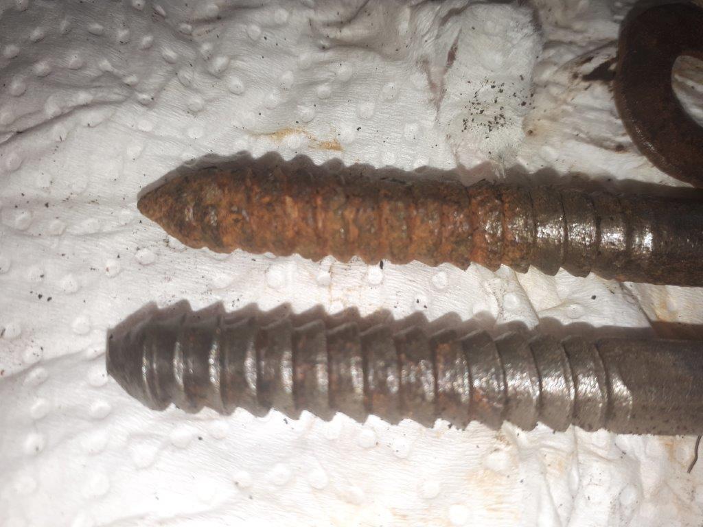
First, we dug a trench around each sides of the structures, set some screws in the bottom of the post on their sides so the cement will have something to grab on, locking the post solidly into the cement.

Off the grid cement mixing :-)
My generator is providing the power to the cement mixer.
Easily handled 2 bags at a time, 3 would had been pushing it.

Both sides done with their cement "boots"

That is 7 bags of 66 lbs cement on each sides for a total of 924 pounds.  All told the total weight should approach close to 1000 pounds, should be grounded solidly this time.

Then I fasten boards on both sides of the greenhouse metal frame.
I used metal strapping and screws. 
The wonkiness on the sides are caused by the still  wonky frame members.
The outside boards are to receive the special fastener for the plastic.

Then  it was just a matter of making up two wood frames to fill in the ends, put a door and windows for ventilation etc.  I had no plans, and worked with what I had on hands.  She went out and bought the special plastic and came back with Qty 10 2X4X8, 10 pieces of 1X3X8  strapping and Qty 6, 1X6X8 boards.  I scrounged what I could around the house for any pieces of 2X lumbers I could find.


It was quickly obvious that I did not have much wood to work with.  So I had to improvised as I went along.

First I put down a thick piece of lumber, roughly even with the sand floor.
The stick in  the middle mark my center of the opening.

I have an aluminum storm door to install, so I took my measurements
 for the door opening from it.

This is what I came up with to fill the frame with my limited amount of wood.
The wide pieces in the bottom give me enough support.
Instead of trying to match the irregular shape of the metal frame, I simply went straight across it.
The last piece on the right is a goof.  Cannot afford too many.
All the cuts are 90s and 45s or close to, easily done on a power miter box.


Took me two goofs to finally figured out why my carefully prepared template got me wrong, twice...


See, the template fit perfectly...

Used it to cut my 2x4 and it is too short...???

Aligned perfectly with my template...
See anything wrong yet??

My template is wider than my 2X4
When lining up my template if I used the bottom, versus the top of it,
 I get a smaller piece at the correct angle...DOH! 

And to think that both time I used my precious template was to "ahem" save on my wood pile by not making costly mistakes...That and I was tired, been under the sun too long and Yaddy Yadda.  But still, annoying!

Then I attached both ends together at the top by using the strapping boards
It really stiffen it up.

Now, how to attached the wood frame to the metal frame.
I resorted to small pieces with a slot to capture the frame.

Drilled a hole centered near the edge

Quick work with a chisel to squared up the sides.


The wooden frames solidly attached to the metal frames.
Joined at the hip :-)
Now ready for the end panels

For the ends panel we recycled the original ends pieces 

End panel attached up front

Stapled and sandwiched with wooden battens around the structure.
These will attach the special rails to it for the top plastic.

Both ends done.  All possible points which could puncture the plastic
 have been rounded and covered with tape at possible rub points.


And then it was time for the special greenhouse plastic.  If you are building a green house, DO NOT use the regular house vapour barrier plastic found at your big box stores.  You need special green house plastic, UV stabilized, won't harden and crack.  Not that expensive and very much worth it.
5 years warranty, which is about all I expect from this structure.  It is temporary
 
Greenhouse plastics comes in various width, we choose 32 ft wide by 40 feet long.  In insight, the next size down, 24 ft would had probably be enough.  Why 40 ft?  cause she wanted to double the cover.
We did not so we have a lot of plastic left over.
Not to worry, we will simply built another with it :-)
Try to pick a day without wind, so much easier :-)


Wanted a door, but had nothing on hand, so I simply framed 
the opening same as the front one.


This is how the plastic is attached securely
That track and spring clip makes it so easy and very strong.
No staples, no puncture of plastic,  That is the way to go.
Hint, that is the system they used on commercial greenhouses.


Next up was to bring in power and ventilation.
Bought a simple box fan at the store and built an enclosure box for it to put in my door opening.
Again, more head scratching, cause I'm really running low on lumber by then...

I'm not joking when I said I was running low on lumber.
That last mistake cutting the diagonal too short, had me resort to an uncommon source.
Notice the greenish colour of it?


Now you see it...
Now you don't :-)
That's right I used one of my boards on the cutting grid :-)
That poor board was too long and sticking out, so it came out to play.
I built that thing in 1995, its been around ...

Box fan, boxed.
I used screws for the whole thing so I can take it apart easily to retrofit a door if ever.
She laid down a weed barrier fabric on the floor.  Much easier to keep clean :-)

Made the box into a rain hood.
Still need to tuck in some loose ends around

Installed a security lite.
I thought it was solar, nope, it used 4 D cells.  Hum, will see how long it last.

Work great .


So now, I have to bring in water and hook up her sink inside.  I will need to excavate a trench for bringing in the water lines to a water point to service the green house, orchards and vegetable garden.
That and a waste line from greenhouse sink.

Meanwhile, she has started moving in already 

This will take a while....
From portable greenhouses, basement and shed etc...


What is left from my pile of wood.
At today's Covid prices, worth about $75 :-(


To say that she is happy, would be an understatement :-)
I can now return to my other projects on the go ... 

Bob, tired, sore but happy.  I got lots of Brownies point in the bank :-)


Friday, May 7, 2021

Champion Blower & Forge Co Post Drill No 96

Still have not found any model number in the usual suspects locations, but did ID it in a 1926 catalog

So what I have here is a Model No 96.  Quite the deluxe model, does not seems to come up very often.

It is a two speed, quick return, auto feed model.  Can also be adapted to power with a pulley, max 250 RPMs.  Boy that would be throwing oil and grease everywhere at that speed :-)

By 1926 it sport a thrust ball bearing,
mine does not and also shows up in the 1907 catalog


I also seen drawing with ball bearings features from the 1902 catalog

Found this pic, one of the rare few, of a model No 96.  Note that one has ball bearing.

That is the look I am after, except obviously mine 
will be mounted on a post as it is supposed to be.
You can drill in the middle of a 15-1/2 in circle.
Will drill up to 1-1/2 in holes in metal.
That drill has a 3 in quill range, with the added Jacobs chuck, 
you really cut down on the range, or do you??
Pic from Pinterest


You may notice also that this model never sported a handle on the top gear as they mostly do.  That is because the quick return lever makes that unnecessary.

I do not know, yet, when they introduces ball bearings in their models, but they been making this model since 1896.  Guessing mine is from the turn of the century.  That would make her 121 years old approximately.  Not quite twice as old as me.

My first thoughts were to make a wooden table, shimmed it square to the drill quill.  But that would again reduced my range drastically... Unless.

Yes I could use a longer post.  That chunk of solid steel would be anything but cheap.  Using a hollow post?  Not really necessary.
You see, the work table top can swing out of the way to reveal a large opening between the forks
You can now drill down on longer pieces and get your clearances back.
Or, swing the whole bracket to the side.  I also seen the tube separated from the drill body and relocate lower.  Or, simply make a lower table to accommodate longer Wood Working bits.  Many options without having to lengthen the post. 
One mod I would make for sure, is to install a Jacobs chuck under the fixed 1/2 in chuck.

All that is making me re-think the proper location on its post.
Will have to experiment again.  Now that the back board is removed from it, would be a lot easier.

With the hardware attaching the drill to its back board, removed,
I could separate the two.
But I had one square lag bolt that gave me a hard time, 
look how tight the wood was packed around it. Bottom lower right.
I was forever turning with an open end wrench ...

The back board.  Looks like from a nominal 2X6 construction lumber.
But it is not SPF, more like some hardwood.  Very dense and heavy.
Beveled edges, stained, then coated copiously with lubricants. 

Where she stand now.  Still unable to remove flywheel.
Need a gear puller for sure.

I keep picking at it, should be pretty well scraped and ready 
for a quick cleaning degreaser then paint, soon, my minion :-).


Similarly, my plans to remove the damaged gear is stalled.  Removed locking screw, but unable to spin out the handwheel on top.  Removed screw thru it, which I found out is acting like an anti rotation of the jack screw enabling it to push or pull the quill when turning the top handwheel. So now I really mucked up its position and will need re-adjusting.  No big deal.  How difficult can it be?? :-)

She is still surprisingly heavy, even with all the parts I removed.  So now that I know the model number it was easy to find out how much they claim it weigh.

Not 300 plus, not 200, just a mere 130 pounds!  Shipping code Feather.  Yes, it`s the biggest of the small ones (usually between 60 and 100 pounds) after this one you jump into biggest baddest machines, 300 - 400 pounds and up.  The big guy. 

Still, it`s very awkward to pick up, and you have to be mindful of the rotation of the parts cause, they will pinch you (read seriously bruised you or worse) in a hurry.  It`s a big brute.


Bob, who just found out by asking my wife, that we had throw away gloves all along.  Who knew? :-)

Said He, has he washes his hands one more times.

Thursday, May 6, 2021

Figured out the return mechanism

I have been frankly scratching  my bald spot for a while trying to figured out the lever activated return mechanism.   Judging by the amount of travel the lever did, there is no way I can see it engaging the spindle gear.  Not even close.

Mechanism disengaged

Mechanism engaged.
See how far the handle went?

That is as far as the gear makes it, barely touching.

Then there is the mysterious depth stop (?) which has 4 dents for the set screw.
Does not seems to do anything, within the travel of the rods.


But as it is becoming cleaner and cleaner, I can see more small detail like a keyway on the gear shaft.

More cleaning found a matching slot on the gears, Huh.

You can see the gear and the key slots lined up.
key is removed.
The end screw and washer were previously cleaned.
4 teeth missing.

Managed to rotate the gear, was frozen rusted pretty tight, needed to be shocked back into reality. Lined up with sloping frozen key. 

Try lever mechanism again, and omphh, the rods when further than before, the gears meshed, it's working.  And bonus, retract when swinging back the lever. 

Fully engaged and working.
Notice how much further back the lever moved.
The depth stop makes more sense also.
It actually work in that second hole positions it was found.

Disengaged

 Cool.  Now just need a new gear.

Hoping my local millwright can make me a new one.  But first I must get it out to bring it to him

Looks like I'll have to take off the down pressure handle to take off the gear shaft besides it connected to the damage gears, to slip the gear out of the fork.

The gear in question
Notice the fork that engage and retract the gear.
The only way out is to pull back the shaft.
Notice anything curious about one of the bolts
 holding the other half of the casting together?
Yep, its an hexagonal bolt, not square head.  An obvious more recent replacement.

That Post drill has been gone over some time ago.  The frame was obviously opened up (new hexagon bolts).  But the  amazing amount of dried gunk all over suggest it was a long time ago. 

Foot assembly has been taken apart, need a good scraping, derusting etc

Today bought some supplies.  Decided to paint the frame mat black.

Thinking gloss black will look too jarring if I cannot paint every parts without a complete disassembly.  Then I'll highlight the lettering with white paint. 


Got the hardware for the post downstairs, big bolt, washer and nut.
Forgot washers for lag screws, oups, and gloves.
and looks like I also forgot a washer for the bolt.

I was going to buy more Krud Kutter then I spotted this.
Thinking that be great just before painting.
Lots of oil and lubricants all over the poor thing.


After looking at the 3 lag screw out of the bath and brushed,
 too much rust damages, won't trusted them to hold the weight solidly, 
These are the two (2) of the three (3) lag bolts that secured the board mounted post drill to the beam.

Only mystery left is how to take up some of the slack on the drill quill attached to the down pressure wheel.  Guessing the big brass nut that joined them up.   I do not have a wrench big enough, need 1-3/8 inch size wrench.

 Tomorrow list :  Washers for lag bolts, , washer for big bolt, gloves, 1-3/8 wrench

After watching a few videos' on Youtube on similar post drills, came to the conclusion that the flywheel wheel should go off and on a lot easier.  May still need a gear puller, but should not required one.  shaft must have too much rust bloom on it.  Gave it a quick sanding and lube, but not enough apparently.

Tomorrow I have a Rotary business meeting on Zoom, that should take up a lot of my time.  That and her brother is coming over to help with her greenhouse.  May not get much time on the Post drill, but should get those missing items.

Even with all the parts removed already, some being quite heavy, I am surprised at how much wat is left weigh.  Still very heavy.

Bob, who washed his hands a bazillions times already, get some gloves idiot!! :-)